6502 Emulator Optimization & Experiments
- arman valaee
- Oct 7, 2022
- 5 min read
Updated: Oct 13, 2022
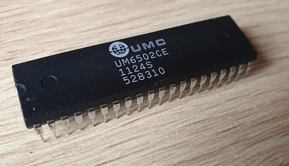
6502 Processor is a widely used processor which was introduced in the mid-1970s. It got popular among many other processors which were already in the market because of its low price. It was priced at 25$ which was way cheaper than any other processor of its time.
This processor has been used in many different famous devices such as Apple II, Atari 400, 800, BBC micro, and...
In this blog, I want to use the 6502 Emulator assembly language for testing and experimenting reasons. After this, we will be much more familiar with the environment of this assembly language.

Part #1 - Sample Code Performance Calculation
In this part, we are given a sample 6502 code which will color the whole 32*32 screen provided by 6502 in yellow color.
Here is the sample code:
	lda #$00		; set a pointer in memory location $40 to point to $0200
	sta $40		; ... low byte ($00) goes in address $40
	lda #$02
	sta $41		; ... high byte ($02) goes into address $41

	lda #$07		; colour number

	ldy #$00		; set index to 0

loop:sta ($40),y	; set pixel colour at the address (pointer)+Y

	iny			; increment index
	bne loop		; continue until done the page (256 pixels)

	inc $41		; increment the page
	ldx $41		; get the current page number
	cpx #$06		; compare with 6
	bne loop		; continue until done all pages
In this code, we use a limited number of simple commands such as LDA, STA, INC, and BNE which is a branching command.
Each one of these commands has a cycle based on its job. Using the 6502 Instruction Set we can understand the cycling number required for each of these commands.
Since we have 2 nested loops in our code, we also need to understand how many times each command will be executed.

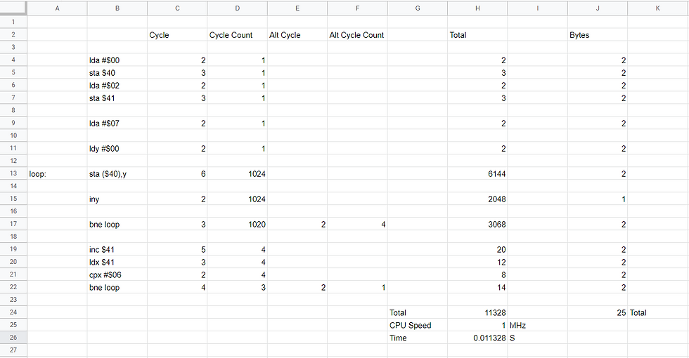
In this spreadsheet, you can see the number of cycles required for each command. There are also the numbers of cycle counts which indicates the number of them executed.
By multiplying the cycle and the cycle count we get the complete cycles of each command.
This program takes 11328 cycles to complete. The number of cycles by itself will not give us the execution time of a program. We also need to know the CPU clocking speed to calculate the execution time. Luckily, we know that the clocking speed of 6502 CPU is 1 MHz. This means that It takes 0.000001 seconds for 6502 CPU to do a single cycle.
With our total of 11328 cycles, we can easily calculate the final execution time which is 0.011328 seconds.
Calculating the total memory usage is a simpler task. In addition to the cycle, each command uses a number of bytes in our memory. The sum of those bytes is our total memory usage which in this case, it is 25 bytes.
Part #2 - Optimizing The Sample Code
This program can be executed in a much shorter time. In this case, it may not matter since it is a small code snippet, but on larger scales, it can make a big difference.
Apparently, the fastest execution time for this program is under half of our calculated time. After trying multiple ways I could not figure out the fastest way but I am gonna share a different approach which it will take longer to execute.
This might sound useless, but it is interesting since it's a different approach to coloring the whole screen.
	lda #$00						;
	sta $40						;
	lda #$02						;
	sta $41						;

	lda #$07						;
	ldy #$00						;

loop:sta ($40),y					;

	inc $41						;
	sta ($40),y					;
	inc $41						;
	sta ($40),y					;
	inc $41						;
	sta ($40),y					;

	dec $41						;
	dec $41						;
	dec $41						;

	iny							;


	bne loop						;
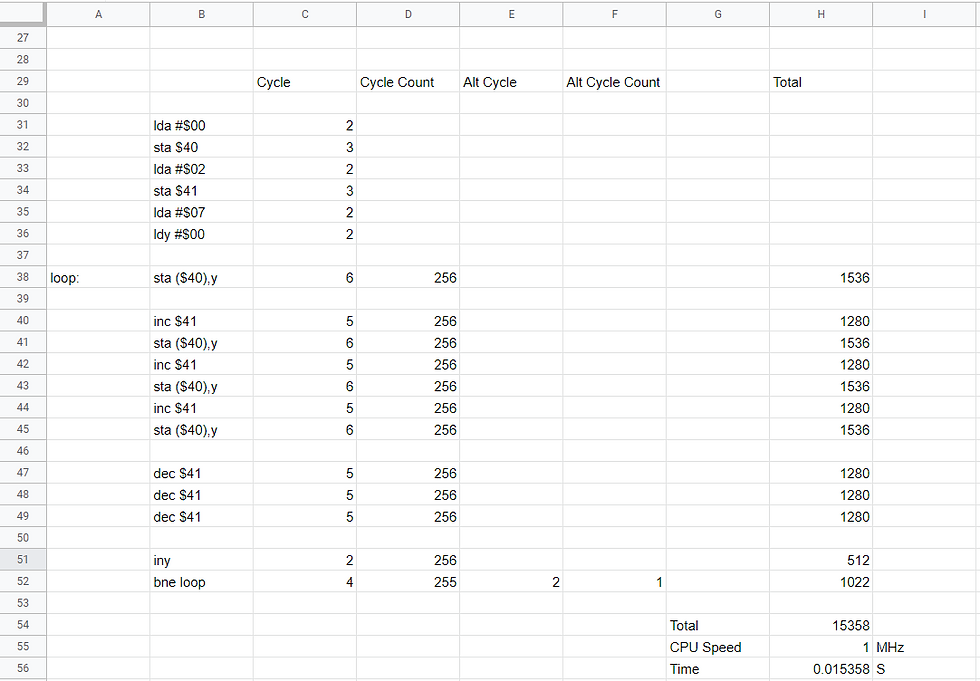
In this approach we color all 4 pages at the same time. We color the first box in the first page, then to the next page. After doing the same thing for all 4 pages we go back and color the second box and so on.
In the spreadsheet below you can see how long it takes for this program to get executed.

I believe one of the faster ways to run this program is to not use any kind of loops and write the STA ($40),y, INC $41, and INY command as much as needed. In this case we will have:
1024*6 for STA ($40),y command
1023*2 for INY command
5*3 for INC $41 command
and 14 for the first memory allocating commands
In total it will take 8219 cycles to complete which is lower than our sample code, but it has an incredibly large memory usage.
Part #3 - Modifying the code
1. Changing The Color
Changing the filling color of this program is a fairly easy task to do and it doesn't need many modifications. The color of this program is specified in one line of the code which is LDA #$07. This is the color code for yellow. We can simply change this line to any other code from the list below:
$0: Black
$1: White
$2: Red
$3: Cyan
$4: Purple
$5: Green
$6: Blue
$7: Yellow
$8: Orange
$9: Brown
$a: Light red
$b: Dark grey
$c: Grey
$d: Light green
$e: Light blue
$f: Light grey

This is how our screen will look like after using the cyan color code which is $03
2. Changing The Color of Each Page
In this task, we need to change the color of each page while filling the screen. After the execution of our program we should have 4 different colors visible on the screen. One for each page.
We know how to use color codes and accumulator to color the screen, and we also know how to go to the next page. By combining these two we can complete this task.
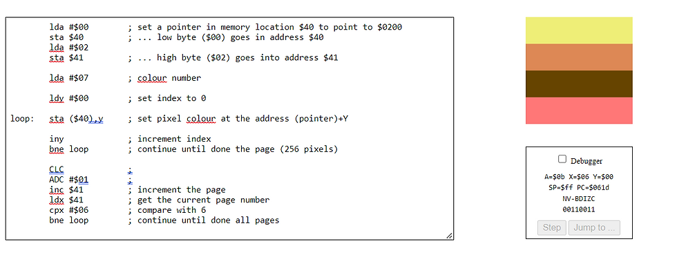
After the first loop in our code, we tend to change the page. In this part, we will change the color code in addition to the page. For this matter we can just add one to the accumulator value using ADC command. We should be aware that the carry flag can affect this operation so the best practice is to clear the carry flag using CLC before the operation.

This is the result of adding CLC and ADC in our loop. We can do this using different colors or by adding more than 1 value to the accumulator.
Part #4 - Experiments
1. Add this instruction after the loop: label and before the sta ($40),y instruction: tya
	lda #$00		; set a pointer in memory location $40 to point to $0200
	sta $40		; ... low byte ($00) goes in address $40
	lda #$02
	sta $41		; ... high byte ($02) goes into address $41

	lda #$07		; colour number

	ldy #$00		; set index to 0

loop:tya			;
	sta ($40),y	; set pixel colour at the address (pointer)+Y

	iny			; increment index
	bne loop		; continue until done the page (256 pixels)

	inc $41		; increment the page
	ldx $41		; get the current page number
	cpx #$06		; compare with 6
	bne loop		; continue until done all pages
This is how the screen will look like after adding TYA before the STA ($40),y and after the LOOP commands.
To understand why this happens, first we need to understand the TYA command.
TYA will transfer Y register value to the accumulator. Since the program is using Hexadecimal values and we have 16 color codes, there are 16 colors visible vertically. The 16 colors are repeated twice in the screen.
Thats because the Y register is getting increased by one on each loop and transfer its value to the accumulator and after F it will overflow and start from the first color again. Each row has 32 pixels so we need 2 set of 16 colors to fill it up.


Comments